

From ltaly to serve the world
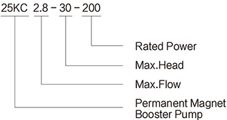
KC
TECHNICAL DATA:
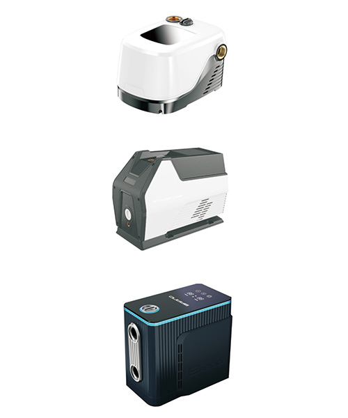
PERMANENT MAGNET VARIABLE FREQUENCY
INTELLIGENT CONSTANT PRESSURE
HOUSEHOLD BOOSTER PUMP
Dual sensing control
Water shortage protection
Incoming water self inspection
Overheat protection
Anti Freezing
Rust prevention and anti jamming
| Model |
Voltage (V) |
Power (W) |
Rated flow (m³/h) |
Max. flow (m³/h) |
Rated head (m) |
Max. head (m) |
Max. lift (m) |
Max. pressure (Mpa) |
Pipe diameter (mm) |
Seed (rpm) |
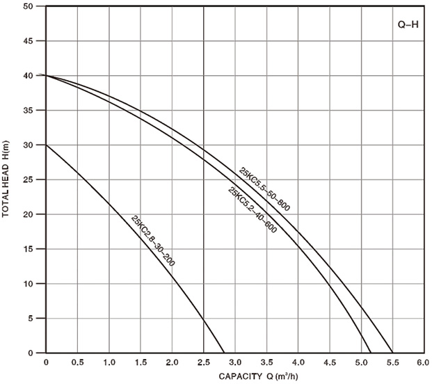
| 25KC2.8-30-200 | 170-270 | 200 | 1 | 2.8 | 15 | 30 | 5 | 0.6 | 25 | 500-9000 |
| 25KC5.2-40-600 | 170-270 | 600 | 2 | 5.2 | 30 | 40 | 6 | 1 | 25 | 5000-6000 |
| 25KC5.5-50-800 | 170-270 | 800 | 3.5 | 5.5 | 30 | 50 | 8 | 1 | 25 | 5000-6000 |
Home Booster Circulating Pump
1.The top discharging point (tap or shower head must be at least 1 meter below the water level in the tank.
2.Take care not to instal tapping point on the pump suction side. Accident opening may cause water backfow or air infow into the pipe work,
where pump does not perform stably.
3.Take care not to install pump on the boiler discharging side, so that to avoid damage or life loss caused by hot water.
4.Keep the inlet pressure no less than 0.01 MPa and no more than 0.6MPa.
5.Install the pump indoor and maintain protecting works against water, dripping, or frostbite
6.lf long suction pipe is installed, keep the tap open for 5 to 6 seconds then pump starts is suggested in the case of exceeding the storage
time limit.
7.Note:
7.1 Before installation, keep the pump in a place no more than 1 year, where temperature is -10°C to 40°C , humidity is
below 80%, and free of corrosive gas, Regular inspection by professional
7.2 Pressure testing or leakage testing is strictly prohibited for pump with connected pipe work, taking due account of
preventing pump from obsolescence,damages, or life loss
7.3 All home booster products are marked as IP code 42(ingress protection rating), and apply for 0.6Mpa max,system
pressure. Products are manufactured and delivered with 1.5m wire as factory standard ,Operating instruction Install the
pump. Switch the shift-knob onto ll (Auto) position and keep the flow rate at 2.5L/min(1.5m/h) so that pump starts
automatically according to tapping point start-stop. Pump works uninterrupted when shift-knob is onto lll (manual)
position. Before starting maintenance work on the pump, keep the shift-knob onto l (stop) position. In the case of faulted
auto function, it is suggested to keep the shift-knob onto lll (manual) position for emergency.
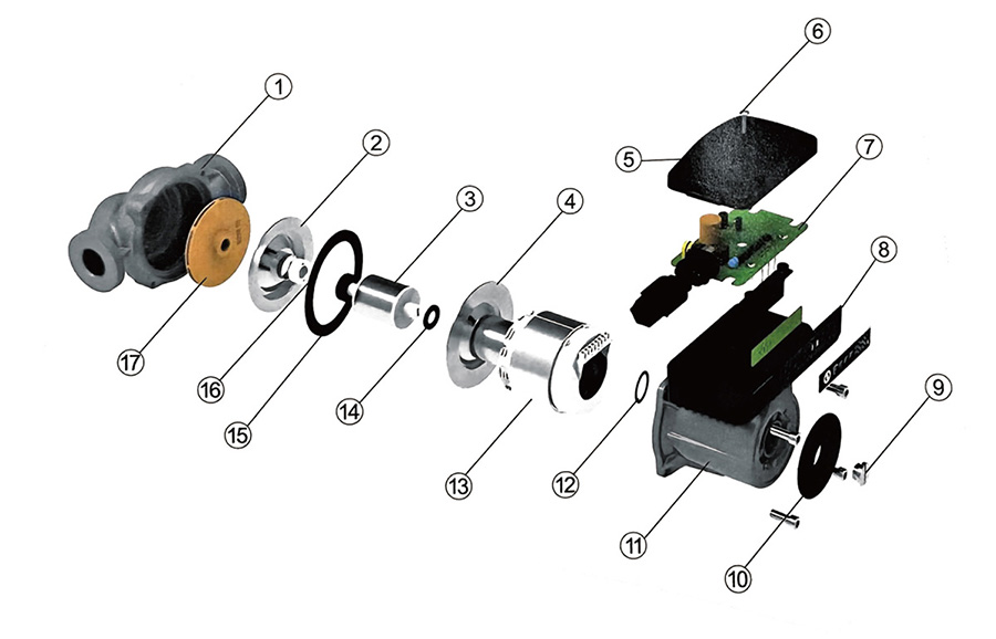
| N0. | Description | N0. | Description | N0. | Description |
|---|---|---|---|---|---|
| 1 |
Pump Body |
7 |
Mcu Board |
13 |
Stator |
| 2 | Ceramic Bearing Seat | 8 | Control Box Seat | 14 | Gasket |
| 3 | Rotor | 9 | Venting Screw | 15 | Thrust Bearing |
| 4 | Stator S.s Shield | 10 | Name Plate | 16 | Gasket |
| 5 | Control Box Cover | 11 | Motor Housing | 17 | Impeller |
| 6 | Screw | 12 | Gasket |
SERVICE AND PURCHASE


ZHEJIANG KEPEIDA PUMP INDUSTRY CO.,LTD
Add: No. 9, six-lane Ding Ke Road, Daxi Town, Wenling City, Zhejiang Province, China
Copyright © ZHEJIANG KEPEIDA PUMP INDUSTRY CO.,LTD. all rights reserved


